Membrane Element Fields Reference
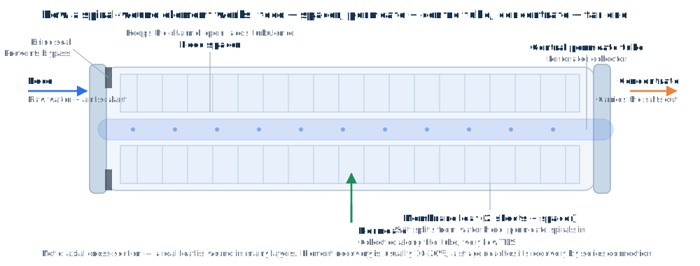
This document covers every field in the “System → Element Management” edit dialog and in CSV import/export. Each field is described three ways: purpose (engineering meaning), calculation (its role and formula in the engine, with the code location), and test method (how the manufacturer measures it, which is also the basis for creating or checking an element).
Qp permeate flow (gpm), A water permeability coefficient, B salt passage basis, NDP net driving pressure (psi),
β concentration polarisation factor, r element recovery (fraction), T water temperature (°C), scc salinity (osmotic pressure) correction, tcff temperature correction.
Code locations are written as internal/calc/ro.go:function() and can be searched directly in the source.1. Basic information fields
| Field | Unit | Purpose | Calculation · test method |
|---|---|---|---|
| Name (ename) | — | Unique identifier of the element model; shown in element selection on the Design page and per-element rows on the Result page | Calculation: used as the element cache key (internal/calc/ro.go:buildElemFactors() looks up ElementData).Test: the manufacturer's model designation (e.g. ESPA2-LD). |
| Code (code) | — | Series code, used for product-line identification and automatic size-code parsing | Calculation: does not take part in the physics (since V58 every “decide by code string” branch has been migrated to explicit parameters, see 4.5); used only for size-code parsing (auto-filling diameter/length) and display. Test: the manufacturer's series code. |
| Brand (brand) | — | Brand ownership: a brand portal shows only that brand's elements | Calculation: not part of the physics; used for data isolation and grouping. Brand staff maintain it in the brand back office; the platform administrator can maintain the whole library. |
| Description (description) | — | Short note on the element, shown in the element selection dialog | Not used in calculation. |
| Family (family) | integer | Membrane family: 1 = SWRO seawater, 2 = BWRO brackish, 5/15 = special seawater correction families, 8 = NF nanofiltration, 9 = high-temperature membrane | Calculation: ro.go:isEspFamily() / ro.go:calcDivalentCation() — with family=5/15 the permeate coefficient is multiplied by factor1 and divalent passage by divcSpfactor; family=7 takes the HYDRA branch.Test: manufacturer product-line classification, not a measured value. |
| Diameter (diam) | inch | Element diameter: 4 inch (domestic / small) or 8 inch (industrial standard) | Calculation: affects the default element count after selection (7 per vessel for 8 inch, 6 for 4 inch) and list grouping. On creation it is parsed automatically from the size code in the code field (8040/4040/2540…). Test: physical measurement of the outside diameter. |
| Length (length) | inch | Element length (standard 40 in) | Calculation: also parsed from the size code; does not affect the hydraulic calculation. Test: physical measurement. |
| Membrane area (area) | ft² | Active membrane area (8 inch standard 365 / 400 / 440 ft²): the basis for capacity and flux conversion | Calculation: permeate flow = A × NDP × area × 1e-5 × scc; flux (lmh) = permGPM × 0.2271 × 1000 ÷ (area × 0.092903) (ro.go:simulateVesselChain()).Test: manufacturers calibrate the active wetted area by liquids displacement, not the geometric area; leaf folding is included. |
| Feed spacer thickness (mil) | mil | Feed channel spacer thickness: 34 mil fouling resistant / 31 mil standard / 28 mil low pressure | Calculation: does not enter the formulas directly; its effect shows up in pcoef/dpfactor1 (pressure drop) and bexp (concentration polarisation).Test: physical measurement of strand diameter and thickness. |
| Applicable feed TDS (minTds/maxTds) | mg/L | Applicable salinity window: a selection hint is given below the lower or above the upper limit | Calculation: feeds the operating warnings (feed TDS above the limit prompts a seawater element). Test: manufacturer product positioning plus high-salinity validation tests. |
2. Standard test condition fields
This group describes the manufacturer's “standard test conditions” — the basis on which the published nominal values are measured. When creating an element these must be filled in as a set, so that rejection and nominal flow share one basis; otherwise the back-calculated B coefficient is distorted.
| Field | Unit | Purpose | Calculation · test method |
|---|---|---|---|
| Salt rejection (nrej) | % | Stabilised rejection under standard test conditions; determines permeate quality (and is the main source of the B coefficient) | Calculation: salt passage basis B = (1 − nrej/100) × ATC × pnetn × area × 1e-5.Test: rejection = (1 − permeate TDS / feed TDS) × 100%. Typical brackish basis: 2000 mg/L NaCl, 150 psi, 25 °C, 15% recovery (ESPA2-LD 99.6%); seawater: 32000 mg/L, 800 psi (SWC5 99.8%). |
| Nominal permeate flow (nprod) | gpd | Nominal permeate flow under standard test conditions (the selection basis) | Calculation: not used directly in the formulas; used for selection comparison and as the “nominal flux” reference (= nprod ÷ area, see 4.6). Test: stabilised flow over 24 h under standard conditions (gallon/day), new membrane, no fouling. |
| Test pressure (fpres) | psi | Factory test feed pressure corresponding to the rejection / flow above | Calculation: not in the formulas (capacity is carried by atc); documents the basis and allows A to be back-calculated.Test: feed pressure gauge reading on the test rig. |
| Net test pressure (pnetn) | psi | Net driving pressure under test conditions (test pressure − osmotic pressure difference − permeate back pressure) | Calculation: enters the B formula (above). Test: from rig inlet/outlet pressures and feed/permeate osmotic pressures: pnetn = fpres − Δπ − P(back). |
| Test salinity (fsal) | mg/L | Test solution TDS (brackish 1500–2000, seawater 32000) | Calculation: basis field only. Note: the runtime sp_esp correction uses the element's actual feed TDS, not this field. Test: prepared test solution concentration (by weight or conductivity). |
| Test recovery (prec) | % | Single-element test recovery (typically 15%) | Calculation: basis field (it sets the concentration factor of the test section and hence the osmotic term in pnetn). Test: permeate/feed flow ratio on the test rig. |
| ATC coefficient (atc) | — | Water permeability constant at 25 °C (the A-value basis): the calibrated capacity of the membrane and the single most important capacity parameter in the engine | Calculation: A = ATC ÷ tcff × factor1(seawater family) × fouling factor × (1 + leak); Qp = A × NDP × area × 1e-5 × scc (ro.go:buildElemFactors()). A larger ATC means more permeate but also more salt passage (the A/B ratio is the membrane's inherent selectivity).Test: back-calculate from standard test flow, A = Qp ÷ (NDP × area × 1e-5), then normalise to 25 °C (multiply tcff back). ESPA2-LD ≈ 13.3 (low pressure, high output); seawater elements are lower. |
3. Operating limit fields (basis of the over-limit warnings)
| Field | Unit | Purpose | Calculation · test method |
|---|---|---|---|
| Max feed pressure (fpMax) | psi | Pressure limit of element and housing (brackish typically 600 psi, seawater 1000+ psi) | Calculation: result warning — feed pressure above the limit raises a “severe” notice. Test: type hydrostatic pressure test (5 min hold with no leakage, deformation or rupture). |
| Max temperature (tempMax) | °C | Maximum operating temperature (45 °C for standard composite membranes) | Calculation: feed temperature above the limit raises a “severe” notice. Test: accelerated high-temperature ageing (rejection loss after hot operation must stay below the specified value). |
| pH range (phMin/phMax) | — | Continuous-operation pH window (typically 2–11; short cleaning excursions 1–13) | Calculation: feed pH outside the window raises a “severe” notice (pH also affects salt passage through the correction in 4.3). Test: chemical soak test (flux/rejection retention after soaking at extreme pH). |
| Max differential pressure (dpMax) | psi | Limit on element feed − concentrate pressure difference (typically 15 psi) | Calculation: exceeding it risks telescoping (mechanical damage to the element); the Result page monitors stage Δp and warns. Test: cyclic pressure-pulse test (simulating start/stop shocks). |
| Permeate flow range (permeateMin/Max) | gpd | Lower/upper permeate flow per element: too low gives uneven distribution, too high worsens polarisation and fouling (e.g. ESPA2-LD 22–4000 gpd) | Calculation: an element outside the range raises a “warning” notice in the per-element table. Test: flux uniformity along the element at low flow + accelerated fouling test at high flow. |
| Salt passage range (spbMin/spbMax) | % | Allowed salt passage interval; also the interpolation endpoints of the boron correction | Calculation: phFactorBoron = (0.5 + n3) × spbMin + (0.5 − n3) × spbMax, where n3 depends on pH, temperature and TDS (ro.go:phCorrectionFactor()).Test: statistical envelope of salt passage over varying temperature, pressure and concentration. |
| Applicable water type (waterTypeApp) | — | Applicable source labelling (brackish / seawater / wastewater, multiple choice) | Calculation: selection reference and filter only, not part of the permeate calculation (the runtime water type comes from the Design page). Test: product positioning, not a measured value. |
4. Engine coefficients (advanced fields)
The physical and empirical parameters below come from the manufacturers' data files. If you are unsure when creating an element, copy a same-series element first and then fine-tune.
4.1 Temperature correction coefficients (4)
ro.go:TempCorFact()〕
Salt passage temperature factor: exp( u × (1/(273+T) − 1/298) ), u = uUpto25 / uAbove25| Field | Unit | Purpose | Calculation · test method |
|---|---|---|---|
| Flux temp. coefficient ≤25 (tcffU25) | — | Capacity correction exponent k for the low-temperature range | Calculation: inserted above to give tcff, then A = ATC/tcff×…. Typically 2780 / 2600.Test: variable-temperature flux test — measure flow at 15/20/25/30/35/40 °C and regress ln(Q) on (1/(273+T) − 1/298); the slope is k, fitted separately on each side of 25 °C. |
| Flux temp. coefficient >25 (tcffA25) | — | Capacity correction exponent k for the high-temperature range | |
| Salt passage temp. coefficient ≤25 (uUpto25) | — | Salt passage temperature exponent for the low-temperature range | Calculation: the temperature factor multiplies the per-ion passage (higher temperature means more salt passage). Typically 5800; seawater elements are split 4660/3600. Test: variable-temperature rejection test — permeate TDS at several temperatures at fixed pressure, regressing ln(B) on (1/(273+T) − 1/298). |
| Salt passage temp. coefficient >25 (uAbove25) | — | Salt passage temperature exponent for the high-temperature range |
4.2 Permeate, pressure drop and salt passage basis
ro.go:simulateVesselChain()〕
Concentration polarisation β = exp(0.7 × r) (r = element recovery, 0–1; software limit 1.2)〔ro.go:simulateVesselChain()〕
Salt passage basis B = (1 − nrej/100) × ATC × pnetn × area × 1e-5| Field | Unit | Purpose | Calculation · test method |
|---|---|---|---|
| Salt passage TDS correction (correction) | — | Reference correction for the osmotic suppression of permeate (typically ≈1.07) | Calculation: see scc above; permeate flow is multiplied by scc (saltier feed, less permeate). Test: variable-concentration flux test — flow at fixed pressure for different NaCl concentrations, regressed for correction and the osmotic coefficient. |
| Pressure drop factor 1 (dpfactor1) | — | Channel pressure-drop coefficient 1 (spacer dependent, typically 1.5) | Calculation: see Δp above, using the 1.4 power (turbulence + spacer behaviour); pressure is reduced element by element along the vessel. Test: clean-water Δp test — element Δp at several flows, regressing Δp on Q^1.4 to get the product of the two coefficients, then splitting by spacer type. |
| Pressure coefficient (pcoef) | — | Channel pressure-drop coefficient 2 (typically 0.01) | |
| Leak rate (leak) | — | Permeate-side bypass fraction (O-ring or glue-line defects, typically 0–0.003) | Calculation: A × (1 + leak) — a leak adds “permeate” but lowers rejection.Test: fluorescent tracer, or inversion from permeate TDS at low pressure and low salinity. |
| Factor 1 (factor1) | — | Permeate correction factor for the seawater families (family 5/15) | Calculation: A × factor1 for the seawater families only; 1 elsewhere.Test: manufacturer data files (calibrated from seawater vs brackish flux comparisons). |
| Polarisation exponent (bexp) | — | Exponent basis of the β formula (typically 0.7) | Calculation: β = exp(bexp × r); this software and the manufacturer data files both use 0.7. (The former integer “B exponent” duplicated this and has been merged.)Test: CFD channel simulation plus permeate TDS rise tests at high recovery. |
4.3 pH correction coefficients (rejection vs pH, piecewise)
ro.go:phCorrectionFactor() / ro.go:spFluorideCorrPH()〕| Field | Unit | Purpose | Calculation · test method |
|---|---|---|---|
| coeff1 ~ coeff4 | — | Ion passage polynomial for pH < 7 (rejection falls at low pH) | Calculation: as above, applied to the passage of ions 1–47. Test: pH step test (5.0 / 5.5 / 6.0 / 6.5 / 7.0), fitting permeate TDS relative to pH 7 as a cubic in pH. |
| bwCoeff1 ~ bwCoeff3 | — | Ion passage polynomial for pH > 8.5 (salt passage rises in the alkaline range) | Calculation: as above. Test: pH step test (8.5 / 9.0 / 9.5 / 10.0 / 10.5), fitted the same way. |
| Silica const1 ~ const6 | — | Empirical polynomial for silicate passage versus pH (6 terms including 1/pH² and e^(−pH)) | Calculation: f49 above, active only for pH > 7, result formatted with ToString("0.0") to 0.1.Test: silica standard solution (e.g. 30 mg/L SiO₂) at several pH values, measuring permeate silica. |
4.4 Ion-specific passage factors
Per-ion factor relative to the basis salt passage (1 = same as the basis). For a new element the whole group can be set to 1 (equivalent to the series average), or copied from a same-series element.
ionSPFactor(ion, salt_trans) = ion table Cols[salt_trans + 3] (equivalent to the official get_IonsData(ion, salt_trans + 7))〔iontable.go:ionSPFactor()〕| Field | Unit | Purpose | Calculation · test method |
|---|---|---|---|
| Salt passage factor (spFactor) | — | Overall salt passage scaling factor (extra correction for SANRO-type elements) | Calculation: only when “extra correction = SANRO type”, B is multiplied by this factor. Test: manufacturer data files. |
| Ca / Mg / Na / SO₄ / NO₃ factors | — | Passage of the corresponding ion (divalents are rejected better than monovalents) | Calculation: multiplied into the permeate concentration per ion. Test: mixed-salt test (known composition), measuring each permeate ion and dividing by the theoretical passage. |
| Silica factor (silicaFactor) | — | SiO₂ passage (silica is undissociated, so its behaviour is special) | Calculation: SiO₂ follows B × silica factor × f49 ÷ temperature factor.Test: silica standard solution test (known silica, measure permeate silica). |
| Boron factor (boronFactor) | — | Boron passage (poor on brackish elements, good on seawater elements) | Calculation: boron follows B × boronFactor × f50; f50 depends strongly on pH/temperature/TDS (boric acid pKa = 9.2, passage rises sharply at high pH).Test: boron standard solution (5 mg/L B) at several pH values. |
| Boron temperature factor (borfacttemp) | — | Temperature correction applied to boron passage | Calculation: temperature term added on the boron path above (the original algorithm scales boron passage with water temperature). Test: variable-temperature boron passage test at fixed pH. |
| Salt passage divisor (divcSpfactor) | — | Divisor for divalent ion passage (divalent cation correction) | Calculation: ro.go:calcDivalentCation() — passage of every divalent ion in the seawater families (5/15), and of non-Ca/Mg divalents outside them, is divided by this value.Test: divalent/monovalent separation test (e.g. CaCl₂ versus NaCl permeate). |
| Salt passage column (saltTrans) | integer | Enumeration of the ion passage column (selects which ion-table column is used) | Calculation: Cols[salt_trans + 3] (equivalent to the official column salt_trans + 7). Values 0–8 are valid; anything else is logged at run time and the permeate salinity result is flagged as unreliable.Test: determined by the manufacturer data file; read-only. |
4.5 Engine behaviour parameters (columns added by this project)
These parameters make the original engine's “decide by element code string” logic explicit (migrated in V58) so that each case can be checked and maintained. In practice only the Hydranautics series need configuration; the HYDRA series is detected automatically by family = 7.
ro.go:membraneTdsCorrection()〕
Base: class 1 (CPA) = 1.75; class 2 (ESPA2) = 2.485 (= 5e-05·TDS + 1.485 for TDS<20000); others = 5.1178 (= 0.000229·TDS + 0.5378 for TDS<20000)
Global breakpoint overrides (highest priority, evaluated in order):
TDS < 5294 → 0.000229·TDS + 0.5378
TDS < 608 → −0.000785·TDS + 1.0713
TDS < 100 → −0.0313·TDS + 4.125
TDS < 36 → 3| Field | Unit | Purpose | Calculation · test method |
|---|---|---|---|
| sp_esp base class (spEspClass) | 0/1/2/3 | Selects the base sp_esp curve: 0 = generic, 1 = CPA series, 2 = ESPA2 series, 3 = SWC6 series (base uses generic + extra correction) | Calculation: as above, together with the element's actual feed TDS it determines the salt passage multiplier. Test: manufacturer data files; can also be inverted from a variable-concentration rejection test (permeate TDS at fixed pressure for several TDS). |
| Enable sp_esp (useSpEsp) | 0/1 | Whether the TDS correction above is applied to salt passage | Calculation: when 0, sp_esp is skipped (salt passage is not corrected for feed concentration). Test: manufacturer data files. |
| Extra correction (elemCorr) | 0/1/2 | 0 = none; 1 = SANRO type (B multiplied by spFactor); 2 = SWC4/5 type (special low-temperature tcff path) | Calculation: branch switch inside ro.go:buildElemFactors().Test: manufacturer data files. |
4.6 Computed read-only fields (derived live from the parameters above)
| Field | Unit | Purpose | Formula |
|---|---|---|---|
| Membrane area (m²) | m² | Interface to SI units (flux, specific energy, etc.) | m² = area(ft²) × 0.092903 |
| Nominal flux | gfd | New-membrane flux under standard conditions, to compare with the design flux limit | gfd = nprod(gpd) ÷ area(ft²) |
| Salt passage coefficient B | — | For checking: is it reasonable compared with same-series elements? | B = (1 − nrej/100) × ATC × pnetn × area × 1e-5 |
5. Key formulas
5.1 Permeate flow of a single element
ro.go:buildElemFactors() → ro.go:simulateVesselChain()〕5.2 Net driving pressure NDP
ro.go:simulateVesselChain()〕5.3 Element pressure drop
5.4 Salt passage and permeate salt
5.5 Concentration polarisation β and the recovery solve
ro.go:simulateVesselChain()〕5.6 Membrane ageing (multi-year operation)
ro.go:FluxLossFactor()〕
age = 0 → 1 (new membrane)
age = 1 → (100 − fd)/100
per-year mode (perYear) → (1 − fd/100)^age
first-year mode (firstYear) → 1 − (fd/10) × (1 − fc), with fc = 0.852330634 − 0.0103·age + 0.15006·e^(−age)
Salt passage growth bfact = 1 + spIncrease/100 × coefficient (derived from membrane age)〔ro.go:SaltPassFactorOf()〕6. Field ↔ engine code map
When a parameter seems to have no effect, locate the implementation directly from this table; line numbers move between versions, so searching by function name is the reliable route.
| Calculation step | Code location | Fields used |
|---|---|---|
| Element factor assembly (A/B/temperature/pH/divalent) | ro.go:buildElemFactors() | atc, tcffU25/A25, factor1, foulingFactor(FF), leak, saltTrans, spFactor, elemCorr |
| Temperature correction tcff | ro.go:TempCorFact() | tcffU25, tcffA25 |
| Salt passage TDS correction sp_esp | ro.go:membraneTdsCorrection() | spEspClass, useSpEsp (+ element feed TDS) |
| pH correction (ions/silica/boron/fluoride) | ro.go:phCorrectionFactor(), ro.go:spFluorideCorrPH() | coeff1~4, bwCoeff1~3, const1~6, spbMin/Max |
| Divalent ion passage correction | ro.go:calcDivalentCation() | divcSpfactor, family |
| Ion passage column | iontable.go:ionSPFactor() | saltTrans (ion table Cols[saltTrans+3]) |
| Element-by-element hydraulic/salt march | ro.go:simulateVesselChain() | area, bexp(β), dpfactor1, pcoef, correction(scc), permeateMin/Max, dpMax |
| Membrane ageing (fouling factor / salt passage factor) | ro.go:FluxLossFactor(), ro.go:SaltPassFactorOf() | (Design page) fluxDecline, membraneAge, spIncrease, foulingFactor |
| Osmotic pressure and saturation | saturation.go:OsmoticPressure(), saturation.go:CalcAllSaturations() | (Analysis page) ion concentrations |
| Power and specific energy | power.go:CalcPower() | (Design page) flow/pressure/recovery/ERD |
7. Test methods quick reference (use these to calibrate a new element)
| Parameter | Test | Data reduction |
|---|---|---|
| ATC (A value) | Measure stabilised permeate flow under known standard conditions (temperature, salinity, pressure, recovery) | A = Qp ÷ (NDP × area × 1e-5), then multiply tcff back to normalise to 25 °C |
| Rejection nrej | Measure permeate TDS in the same standard test | nrej = (1 − permeate TDS / feed TDS) × 100% |
| Temperature coefficients tcffU25 / tcffA25 | Variable-temperature flux test (15–40 °C, 5 °C steps, all else fixed) | Linear regression of ln(Qp) on (1/(273+T) − 1/298), slope taken separately either side of 25 °C |
| Salt passage temperature coefficients uUpto25 / uAbove25 | Variable-temperature rejection test (fixed pressure, permeate TDS at each temperature) | Slope of the regression of ln(B) on (1/(273+T) − 1/298) |
| correction (scc) | Variable-concentration flux test (e.g. 500 / 1000 / 2000 / 3500 mg/L NaCl) | Regress the linear decline of permeate flow with osmotic pressure; the intercept is correction |
| dpfactor1 / pcoef | Clean-water Δp test (element Δp at several flows) | Regress Δp on Q^1.4; the two coefficients appear as a product, then split by spacer type |
| leak (leak rate) | Invert permeate TDS at low pressure and low salinity, or use a fluorescent tracer | Derive the bypass fraction from the shortfall in rejection |
| Ion factor group | Mixed-salt test (known composition) | Per ion: factor = measured permeate concentration ÷ theoretical passage concentration |
| pH polynomial group | pH step test (5.0–7.0 and 8.5–10.5) | Fit “permeate TDS relative to pH 7” against pH (cubic at low pH, quadratic at high pH) |
| Silica const1~6 | Silica standard solution at several pH values | Least-squares fit of the 6-term empirical form (including 1/pH² and e^(−pH)) |
| spEspClass (sp_esp) | Variable-concentration rejection test (permeate TDS at fixed pressure for several TDS) | Divide by the basis B to obtain the correction curve, then classify (generic/CPA/ESPA2/SWC6) |
8. Field maintenance guide
A = Qp ÷ (NDP × area × 1e-5), then normalise to 25 °C;
④ fill the operating limits from the datasheet Operating Limits table;
⑤ regress against a benchmark case (permeate TDS, feed pressure and concentrate TDS for the same array must fall in a sensible engineering range and stay within 1% of the official software).| Scenario | Required fields |
|---|---|
| Selection comparison only (no calculation) | Name, brand, description, area, rejection, nominal flow, diameter, length, spacer thickness |
| Used in design calculation | All of the above + ATC, net test pressure, both pressure-drop coefficients, the four temperature coefficients (copyable from the series), correction, saltTrans |
| Operating warnings enabled | Max feed pressure, max temperature, pH range, Δp limit, permeate flow range, applicable TDS limits |
| Per-ion accuracy needed | Add the ion factor group, pH polynomial group, spEspClass / useSpEsp / elemCorr, divcSpfactor |
CSV batch import: the header matches the “Export CSV” file, a blank ID is assigned automatically, an existing ID is updated; a brand portal can only import its own brand's elements. Internal columns such as the engine slot are no longer shown — the ID itself is the only key used by the calculation engine.
rofilter.cn reverse osmosis membrane design software · membrane element fields reference · formulas correspond line by line to the implementation (temperature correction, pH polynomials, sp_esp breakpoint curve, ion passage columns, 1.4-power pressure drop, β = exp(0.7·r), the two ageing modes)